Support for LILYGO TTGO T8 ESP32-S2 Board. More...
Detailed Description
Support for LILYGO TTGO T8 ESP32-S2 Board.
LILYGO TTGO T8 ESP32-S2
Table of Contents
Overview
The Espressif LILYGO TTGO T8 ESP32-S2 (also known as LilyGo T-Display S2) is a ESP32-S2 board with an OLED Display and a TF Card slot.
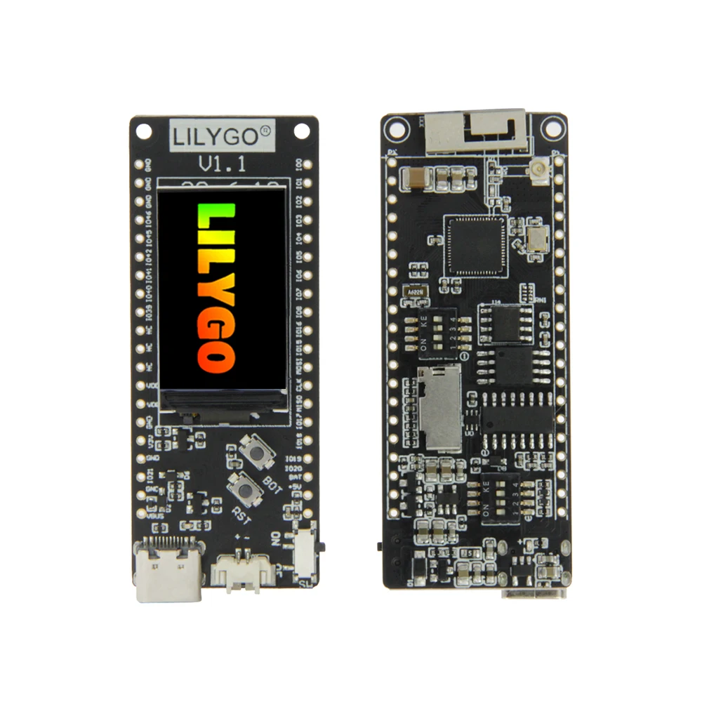
The board has following main features:
| Feature | Support |
|---|---|
| ESP32-S2 SoC | yes |
| 4 MB Flash | yes |
| 8 MB QSPI RAM | yes |
| SD Card slot | yes |
| 32.768KHz Crystal | yes |
| OLED display ST77789 | yes |
Hardware
This section describes
- the MCU,
- the default board configuration,
- the board pinout.
MCU
Most features of the board are provided by the ESP32-S2 SoC. For detailed information about the ESP32-S2 SoC variant (family) and ESP32x SoCs, see section ESP32 SoC Series.
Board Configuration
The LILYGO TTGO T8 ESP32-S2 board uses the SPI_DEV(0) (FSPI) for the OLED Display. The GPIOs of SPI_DEV(0) are therefore not broken out. SPI_DEV(1) is used for the SD Card slot. These GPIOs are broken out and can also be used by other devices.
The LILYGO TTGO T8 ESP32-S2 has a USB-to-UART bridge on board. The USB D-/D+ signals of the USB-C connector are connected via DIP switches either to this USB-to-UART bridge (default) or to GPIO19/GPIO20 of the ESP32-S2. To use the USB OTG interface of the ESP32-S2, the USB D-/D+ signals must be connected to GPIO19 and GPIO20, see section Pinout. To use the USB OTG interface also for the console in this case, either the stdio_cdc_acm or the stdio_tinyusb_cdc_acm module must be enabled. This is automatically the case if the USBUS or tinyUSB stack is used.
The LILYGO TTGO T8 ESP32-S2 has a 32.768 kHz crystal on the board, which is connected to GPIO15 and GPIO16 via DIP switches (default). The crystal can be switched off via the DIP switches so that GPIO15 and GPIO16 become available at the headers, see section Pinout.
The following table shows the default board configuration, which is sorted according to the defined functionality of GPIOs. This configuration can be overridden by application-specific configurations.
| Function | GPIOs | Remarks | Configuration |
|---|---|---|---|
| BUTTON0 | GPIO0 | ||
| ADC_LINE(n) | GPIO1 ... GPIO9 | ADC Channels | |
| DAC_LINE(n) | GPIO17, GPIO18 | DAC Channels | |
| GPIO38 | GPIO38 | OLED RESET (not broken out) | |
| I2C_DEV(0) SCL | GPIO7 | I2C Interfaces | |
| I2C_DEV(0) SDA | GPIO8 | I2C Interfaces | |
| PWM_DEV(0) | GPIO39, GPIO40, GPIO41, GPIO42 | - | PWM Channels |
| PWM_DEV(1) | GPIO15, GPIO16 | if module esp_rtc_timer_32k is not used | PWM Channels |
| SPI_DEV(0) CLK | GPIO36 | OLED CLK (not broken out) | |
| SPI_DEV(0) MISO | GPIO37 | OLED MISO (not broken out) | |
| SPI_DEV(0) MOSI | GPIO35 | OLED MOSI (not broken out) | |
| SPI_DEV(0) CS0 | GPIO34 | OLED CS0 (not broken out) | |
| SPI_DEV(1) CLK | GPIO12 | SD Card CLK | SPI Interfaces |
| SPI_DEV(1) MISO | GPIO37 | SD Card MISO | SPI Interfaces |
| SPI_DEV(1) MOSI | GPIO35 | SD Card MOSI | SPI Interfaces |
| SPI_DEV(1) CS0 | GPIO34 | SD Card CS | SPI Interfaces |
| UART_DEV(0) TxD | GPIO43 | Console | UART interfaces |
| UART_DEV(0) RxD | GPIO44 | Console | UART interfaces |
| USB D- | GPIO19 | if USB-to-UART bridge is not used | |
| USB D+ | GPIO20 | if USB-to-UART bridge is not used |
For detailed information about the peripheral configurations of ESP32-S2 boards, see section Common Peripherals.
Board Pinout
The following figure shows the pinout as configured by the board definition.
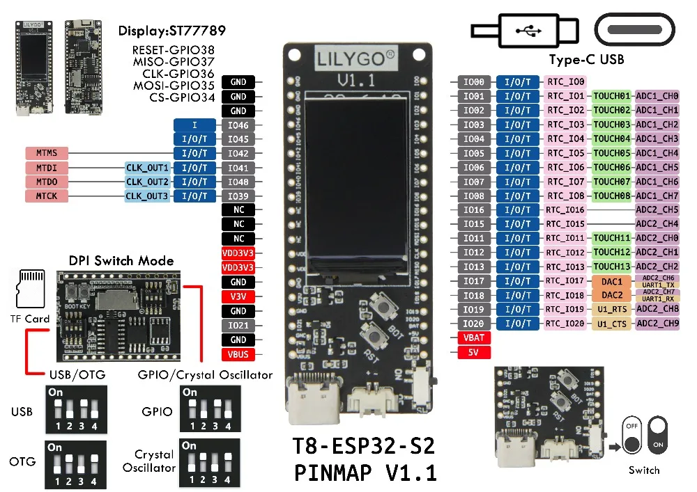
The corresponding board schematics can be found here
Flashing the Device
Flashing RIOT is quite easy. The board has an USB-C connector which is either connected to the USB-to-UART bridge (default) with a built-in reset/boot/flash logic or to the USB signals of the ESP32-S2 SoC. The flash method depends on the configuration of the DIP switches, see section Pinout.
USB-C connector is connected to the USB-to-UART bridge (default)
Just connect the board to your host computer and type using the programming port:
For detailed information about ESP32-S2 as well as configuring and compiling RIOT for ESP32-S2 boards, see RIOT-OS on ESP32 SoC Series Boards.
USB-C connector is connected to the USB signals of the ESP32-S2 SoC
In this configuration the integrated USB-to-JTAG bridge can be used to flash the board. The USB-to-JTAG bridge is automatically activated in the download mode of the bootloader, provided that the eFuses JTAG_SEL_ENABLE and DIS_USB_JTAG are not burned (see also section JTAG Interface strapping pin GPIO3).
For this purpose, connect the board to your host computer and enter the following command using the programming port:
If RIOT is already on the device, it should automatically reset the device and enter the bootloader download mode. If
- RIOT is not already on the device or
- automatic reset does not work or
- the device is stuck in some other mode,
the download mode has to be forced before by pressing the Reset (RST) button while holding the BOOT (BOT) button.
Files | |
| file | arduino_iomap.h |
| Mapping from MCU pins to Arduino pins. | |
| file | board.h |
| Board definitions for the LILYGO TTGO T8 ESP32-S2 board. | |
| file | gpio_params.h |
| Board specific configuration of direct mapped GPIOs. | |
| file | periph_conf.h |
| Peripheral configurations for the LILYGO TTGO T8 ESP32-S2 board. | |
