Support for the Waveshare nRF52840 Eval Kit. More...
Detailed Description
Support for the Waveshare nRF52840 Eval Kit.
Overview
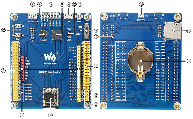
The Waveshare nRF52840 Eval Kit is an evaluation board for the nRF52840 SoC with the following on-board components:
- Arduino headers for connecting Arduino shields
- Raspberry Pi GPIO header for connecting Raspberry Pi HATs
- USB TO UART interface
- USB port of nRF52840
- 4PIN SWD debugging interface for connecting ARM Debugger to program / debug
- 3.3V/5V power input/output provides power output OR powered from external power supply
- Waveshare Core52840: nRF52840 core module
- CP2102: USB TO UART converter
- Buzzer
- RT9193-33: 3.3V voltage regulator
- Optical sensor
- RESET and USER KEY
- 4 User LEDs
- Power switch: USB powered - OFF - Battery powered
- NFC antenna connector
- TF card slot
- CR2032 battery holder
Using the onboard Arduino and Raspberry Pi compatible headers, both Arduino shields and Raspberry Pi HATs can be used at the same time.
Hardware:
| MCU | NRF52840 |
|---|---|
| Family | ARM Cortex-M4 |
| Vendor | Nordic Semiconductor |
| RAM | 256 kByte |
| Flash | 1 MByte |
| Frequency | 64 MHz |
| FPU | yes |
| GPIOs | 48 |
| Timers | 5 x 32-bit counter |
| RTC | 3 x Real Time Counter |
| ADCs | 1 x 12-bit 200 ksps with 8 channels |
| UARTs | 2 |
| SPIs | 1 x QSPI, 3 x SPI master/slave |
| I2Cs | 2 |
| I2S | 1 |
| PWM | 4 * 4 Channels |
| Crypto | AES-128, SHA1/2, RSA, Chacha20/Poly1305, ECC |
| Radio | 2.4 GHz transceiver, Bluetooth 5, IEEE 802.15.4 |
| Vcc | 1.7V - 5.5V |
| Datasheet | Datasheet |
| Reference Manual | Reference Manual |
| Board Manual | Board Manual |
| Board Schematic | Board Schematic |
Pin Layout / Configuration
The following table shows the connection of the on-board components with the MCU pins. All these connections are jumpered and can be removed.
| MCU Pin | MCU Peripheral | RIOT Peripheral | Board Function | Arduino Header | Rasperry Pi (*) |
|---|---|---|---|---|---|
| P0.02 | ADC | ADC_LINE(0) | AREF | ||
| P0.03 | ADC | ADC_LINE(1) | A0 | P26 (32) | |
| P0.04 | ADC | ADC_LINE(2) | A1 | P27 (36) | |
| P0.05 | ADC | ADC_LINE(3) | Optical sensor (LDR) | P7 (7) | |
| P0.06 | UARTE0 RX | UART_DEV(0) RX | UART RX | P21 (29) | |
| P0.07 | UARTE0 CTS | UART_DEV(0) CTS | UART CTS | P6 (22) | |
| P0.08 | UARTE0 TX | UART_DEV(0) TX | UART TX | P3 (15) | |
| P0.09 | NFC Antenna Connector | P1 (12) | |||
| P0.10 | NFC Antenna Connector | P25 (37) | |||
| P0.11 | BTN0 | Button KEY1 | P2 (13) | ||
| P0.12 | SPI_DEV(1) CS | SD Card CS | CIE1 (26) | ||
| P0.13 | PWM | PWM_DEV(1).0 / LED1 | LED1 | P24 (35) | |
| P0.14 | PWM_DEV(1).1 / LED2 | LED2 | P23 (33) | ||
| P0.15 | PWM_DEV(2).0 | Buzzer | P22 (31) | ||
| P0.16 | PWM_DEV(1).3 / LED4 | LED4 | ID_SD (27) | ||
| P0.17 | SPI1 SCK | SPI_DEV(1) SCK | SD Card SCLK | SCLK (23) | |
| P0.18 | BTN1 | Button RESET | |||
| P0.19 | TXD0 (8) | ||||
| P0.20 | SPI1 MISO | SPI_DEV(1) MISO | SD Card MISO | MISO (21) | |
| P0.21 | RXD0 (10) | ||||
| P0.22 | I2C0 SCL | I2C_DEV(1) SCL | SCL (5) | ||
| P0.23 | CIE0 (24) | ||||
| P0.24 | SPI1 MOSI | SPI_DEV(1) MOSI | SD Card MOSI | MOSI (19) | |
| P0.25 | UARTE0 RTS | UART_DEV(0) RTS | UART RTS | P0 (11) | |
| P0.26 | I2C1 SDA | I2C_DEV(0) SDA | I2C SDA | SDA | |
| P0.27 | I2C1 SCL | I2C_DEV(0) SCL | I2C SCL | SCL | |
| P0.28 | ADC | ADC_LINE(4) | A2 | P28 (38) | |
| P0.29 | ADC | ADC_LINE(5) | A3 | P29 (40) | |
| P0.30 | ADC | ADC_LINE(6) | A4 | ||
| P0.31 | ADC | ADC_LINE(7) | A5 | ||
| P1.00 | I2C0 SDA | I2C_DEV(1) SDA | SDA (3) | ||
| P1.01 | UARTE1 RX | UART_DEV(1) RX | D0 / RX | ||
| P1.02 | UARTE1 TX | UART_DEV(1) TX | D1 / TX | ||
| P1.03 | D2 | ||||
| P1.04 | PWM_DEV(0).0 | D3 / PWM | |||
| P1.05 | D4 | ||||
| P1.06 | PWM_DEV(0).1 | D5 / PWM | |||
| P1.07 | PWM_DEV(0).2 | D6 / PWM | |||
| P1.08 | D7 | ||||
| P1.09 | PWM_DEV(1).2 / LED3 | LED3 | ID_SC (28) | ||
| P1.10 | D8 | ||||
| P1.11 | PWM_DEV(0).3 | D9 / PWM | |||
| P1.12 | D10 / SS | ||||
| P1.13 | SPI0 MOSI | SPI_DEV(0) MOSI | D11 / MOSI | ||
| P1.14 | SPI0 MISO | SPI_DEV(0) MISO | D12 / MISO | ||
| P1.15 | SPI0 SCK | SPI_DEV(0)SCK | D13 / SCK |
(*) Raspberry Pi header pins are given by the labels as used on the board. These labels correspond to the pins and names as used by the 'WiringPi' library. For detailed information on how these numbers are mapped to the GPIOs of the BCM SoCs, see this document. The numbers in the brackets are the pin numbers of the 40-pin header.
Flash the board
See the Flashing section in nRF52 common.
The easiest way is to use a Segger J-Link and connect it to the SWD header of the board as follows:
- Segger J-Link Pin 7 with SWD Header pin
DIN - Segger J-Link Pin 9 with SWD Header pin
CLK
Accessing STDIO via UART
The stdio is directly accessible via the on-board CP2102 USB to UART bridge. On a Linux host, this interface is mapped to /dev/ttyUSB<n> where <n> is the index of the UART interface which is 0 by default.
Use the term target to connect to the board serial port using /dev/ttyUSB0:
If the UART interface index of board's USB to UART bridge is not 0, use the following command to connect to the board serial port:
RESET Pin Configuration
On nRF52840 boards, the RESET pin is not configured out-of-the box. This means, that simply nothing happens if the RESET button is pressed. To change this, RIOT provides a little tool in dist/tools/nrf52_resetpin_cfg:
Simply compile, flash, and run that tool on your board, and the reset pin should work for the time being.
Files | |
| file | arduino_iomap.h |
| Mapping from MCU pins to Arduino pins. | |
| file | board.h |
| Board specific configuration for the Waveshare nRF52840 Eval Kit. | |
| file | gpio_params.h |
| Configuration of SAUL mapped GPIO pins. | |
| file | periph_conf.h |
| Peripheral configuration for the Waveshare nRF52840 Eval Kit. | |
