Support for the ScatterWeb Modular Sensor Board 430. More...
Detailed Description
Support for the ScatterWeb Modular Sensor Board 430.
MCU
| MCU | TI MSP430F1612 |
|---|---|
| Family | MSP430 |
| Vendor | Texas Instruments |
| Package | 64 QFN |
| RAM | 5 KiB |
| Flash | 55 KiB |
| Frequency | up to 8 MHz |
| FPU | no |
| Timers | 2 (2x 16bit) |
| ADCs | 1x 8 channel 12-bit |
| UARTs | 2 (*) |
| SPIs | 2 (*) |
| I2Cs | 1 (*) |
| Vcc | 1.8 V - 3.6 V (battery holder board provides 3.0 V) |
| Datasheet MCU | Datasheet |
| User Guide MCU | User Guide |
| Website | MSB-430 |
- Warning
- While programming, the minimum supply voltage is 2.7 V instead of 1.8 V.
- When the supply voltage supervisor (SVS) (a.k.a. brownout detection) is used, the supply voltage must initially be at least 2.0 V due to the hysteresis of the SVS circuitry. Afterwards the MCU remains operational with VCC >= 1.8 V.
- The MSP430F1612 has two USARTS, which can be configured as UART, SPI, or (only in case of USART0) as I2C bus. Each USART can only provide one serial interface at a time; time sharing is theoretically possible but not yet implemented.
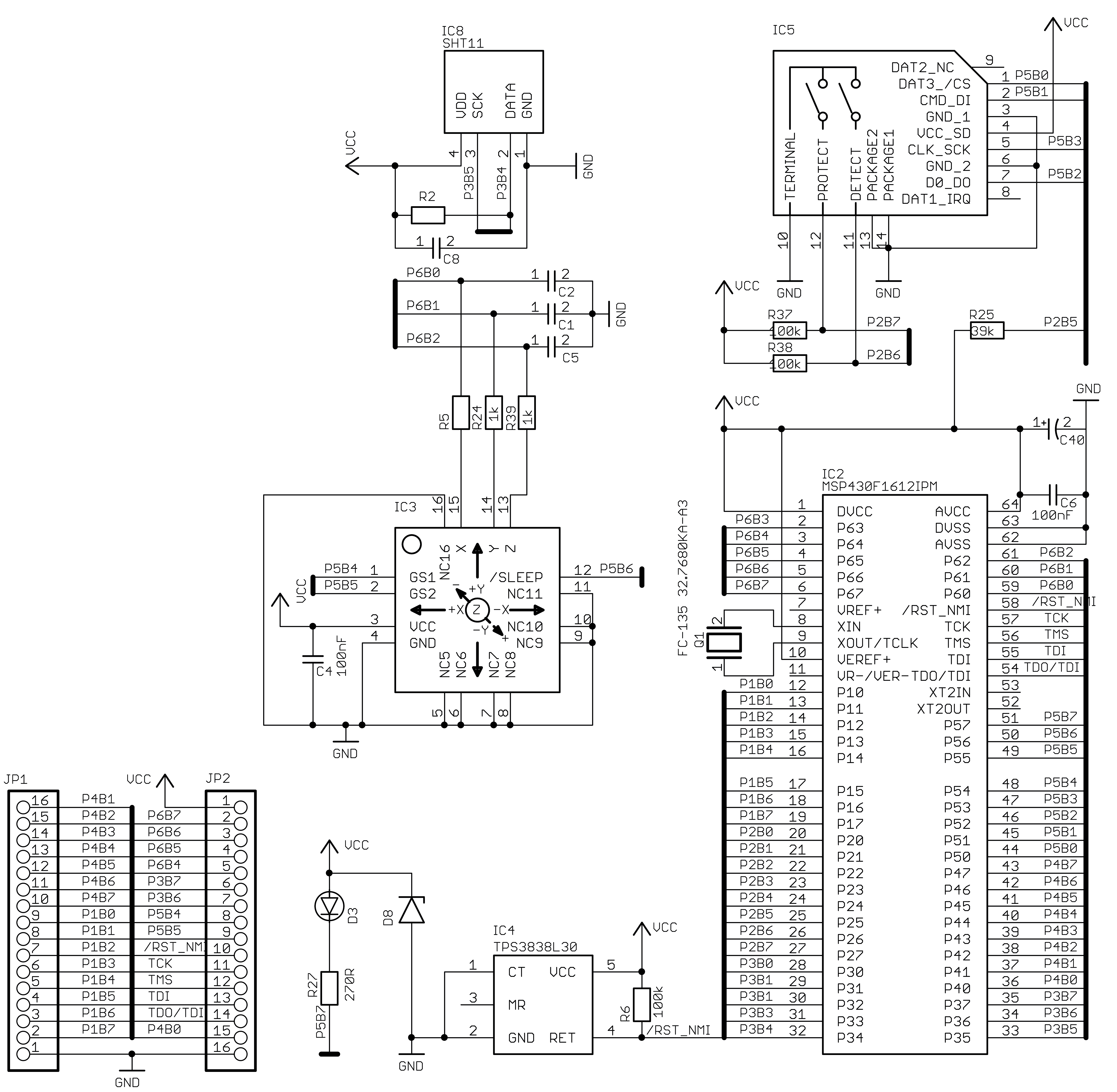
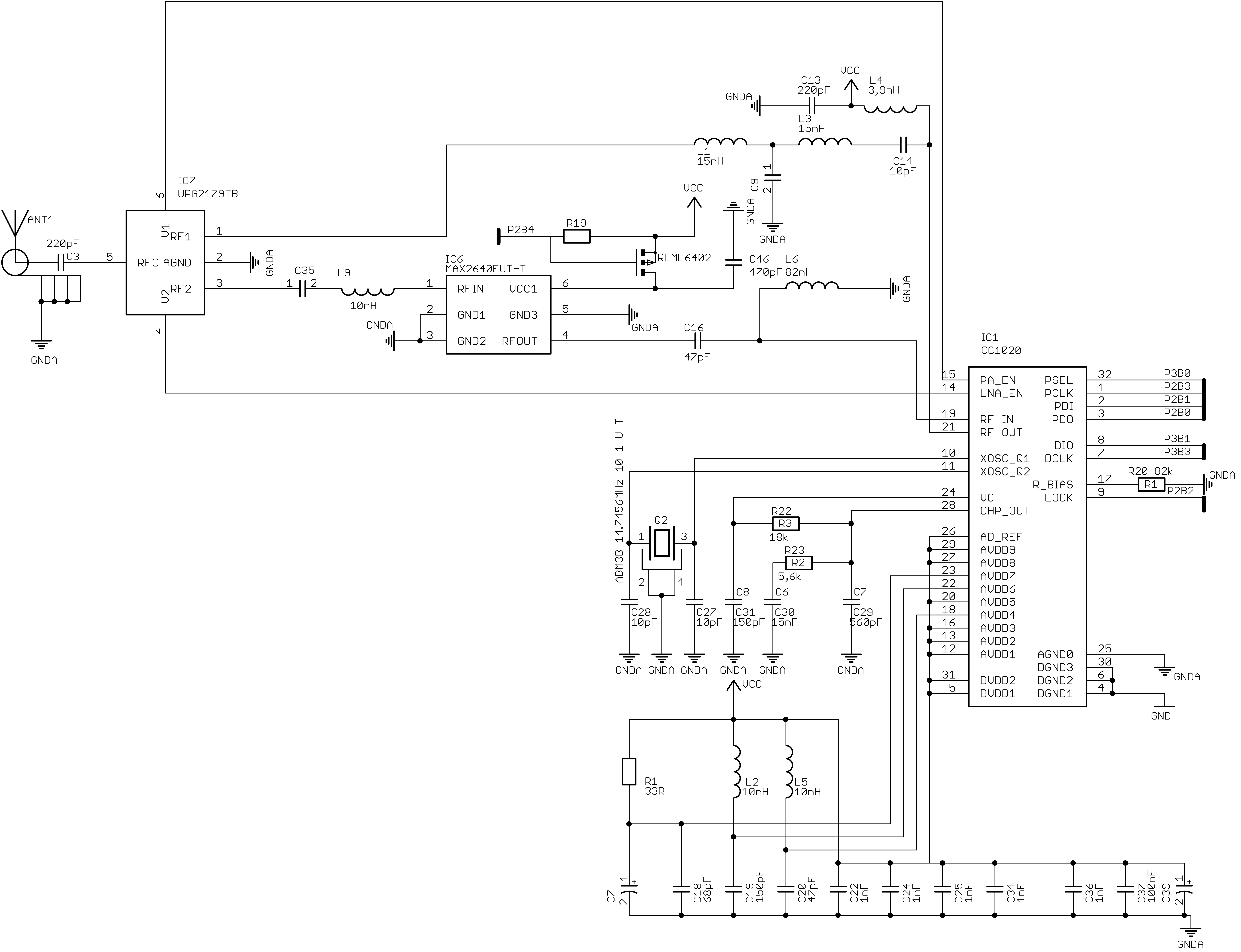
Schematics
Hardware Limitations
The GPIOs on the MSP430F1612 only have two MUX settings: Being used as digital input/output or routed to a peripheral. The MCU has two universal serial synchronous/asynchronous communication interfaces (USARTs), which can be used to provide either an UART, an SPI, or (only in case of USART0) an I2C bus. Every USART signal is available at exactly one GPIO pin.
The UART exposed via the battery holder board (P3.6 and P3.7) can only be provided via USART1. In order to support asynchronous reception (e.g. to allow interaction via the shell), USART1 needs to be continuously configured as UART and cannot be used to provide an SPI bus.
The SPI bus connected to the SD card socket (P5.1, P5.2, and P5.3) can only be provided via USART1. Hence, it is not possible to use SPI bus connected to the SD card socket while the UART used for stdio is in use, as they use the same USART. They could be used at the same time, if module stdin is not used (the UART is output only). However, sharing USARTs is not yet implemented.
The SPI bus of the CC1020 transceiver (used for configuration only) is connected to pins P2.0, P2.1, and P2.3. Those pins are not connected to either USART, so no hardware SPI can be used to interact with the transceiver. However, the SPI is only used for configuration and control of the transceiver, so using a slow bit-banging SPI bus won't affect the performance of the transceiver, other than for quick power down after transmission or channel hopping. A second two wire serial interface (not I2C or compatible) is used to feed data into the CC1020 or read data from the CC1020. The serial clock is driven by the transceiver and the MCU needs to keep up with providing the frames to send bit by bit. Unlike modern transceivers, the CC1020 has no frame buffer and the MCU needs to control the transmission and reception on the bit level.
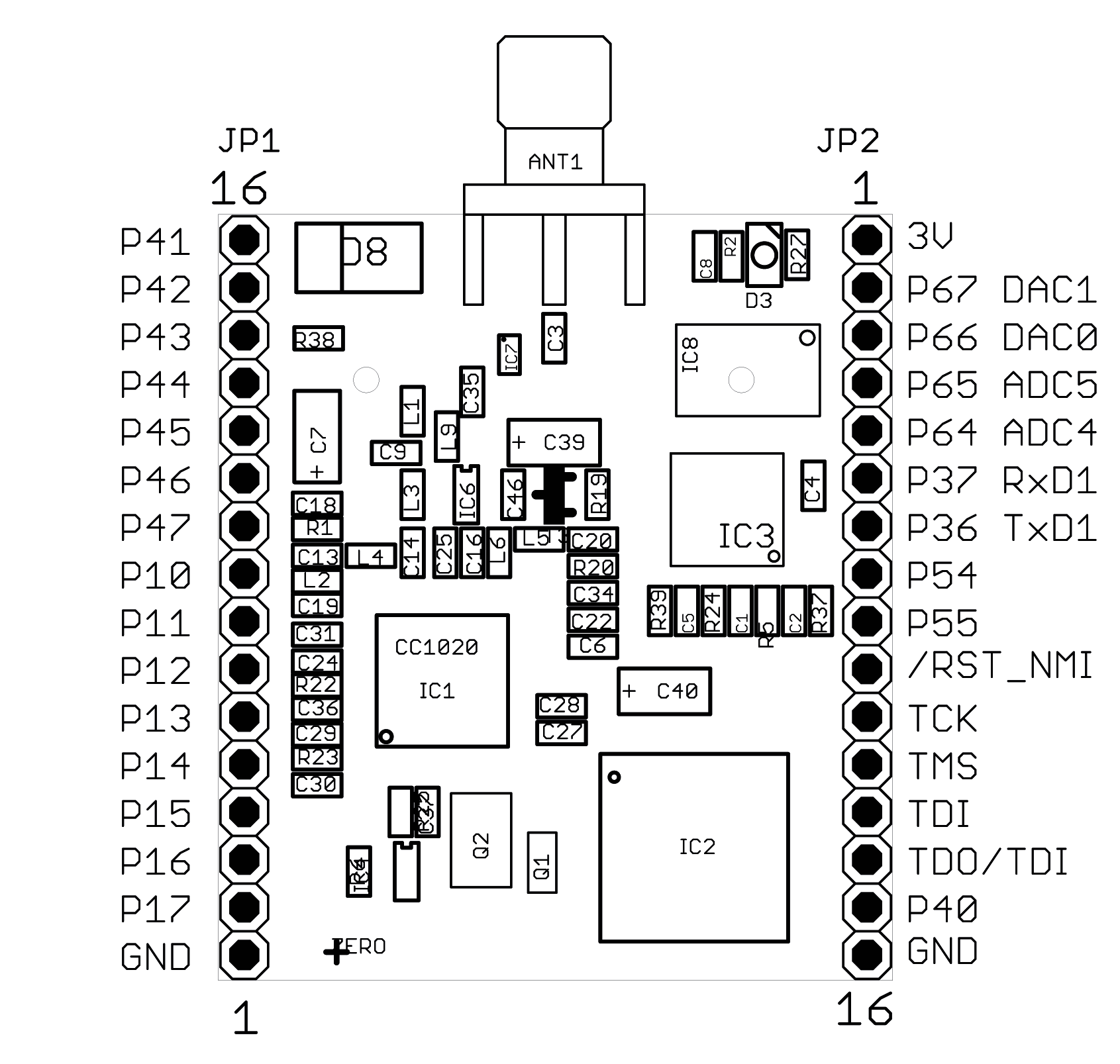
Pinout
Pinout of the Main MSB 430 Board
Pinout of the Battery Holder Board
The pins above the JTAG header with the pin closest to the power supply switch being denoted as Pin 1, the signals are as follows:
| Pin | 1 | 2 | 3 | 4 | 5 | 6 |
|---|---|---|---|---|---|---|
| Signal | GND | NC | 5V | RXD | TXD | NC |
The battery holder board contains a 3V power regular that powers the MSB-430 board via 3V pin (pin 1 on JP2). The switch at the bottom can be used to select the input voltage of that power regulator: If the switch is in the position towards the daughter board, it will use the 5V pin of the header above the JTAG header as power supply, otherwise the batteries are used as power supply.
Flashing RIOT
Place the MSB-430 board into the batter holder board with the SD card socket facing towards the battery holder board and the (likely unpopulated) antenna connector facing away from the switch and JTAG-connector of the battery holder board. (As shown in the picture at the top of the page.)
Afterwards, connect a JTAG debugger supported by mspdebug; by default the Olimex MSP430-JTAG-Tiny is assumed, which is among the less expensive options.
- Note
- If you are not using the Olimex MSP430-JTAG-Tiny (or a compatible programmer), set
MSPDEBUG_PROGRAMMERto the correct value via an environment variable or as parameter to make. E.g. usemake BOARD=msb-430 MSPDEBUG_PROGRAMMER=bus-pirateto flash using the bus pirate.
- Warning
- It is recommended to use the external power supply via the 5V pin instead of the battery while flashing.
Once the board is firmly connected in the battery holder and the JTAG cable is connected, just run
in the application's directory.
Using the shell
stdio is available via the UART interface with RXD = P3.7 (pin 35 on the header) and TXD = P3.6 (pin 34 on the header) at 115,200 Baud.
The easiest way is to connect an USB TTL adapter (such as the cheap cp210x or ch341 based adapters) to the battery holder board as follows:
Files | |
| file | board.h |
| Central definitions for the ScatterWeb MSB-430 board. | |
| file | periph_conf.h |
| MSB-430 peripheral configuration. | |
