Support for generic ESP32-C3 boards. More...
Detailed Description
Support for generic ESP32-C3 boards.
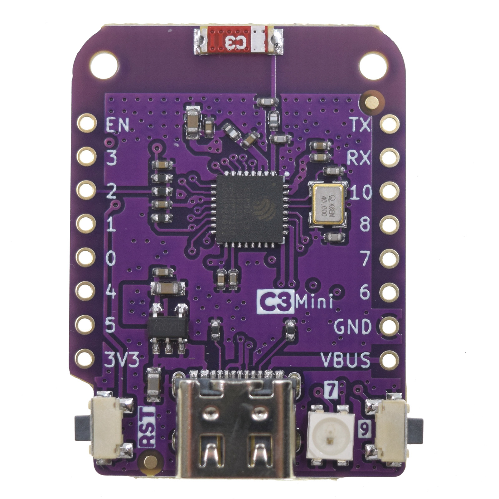
Wemos ESP32-C3 mini
Table of Contents
Overview
The Wemos ESP32-C3 mini board is an interesting development kit as it uses in the stackable Wemos LOLIN D1 Mini format. Thus, all shields for Wemos D1 mini for ESP8266 can also be used with ESP32-C3. Examples for such shields are:
- Micro SD-Card Shield
- MRF24J40 IEEE 802.15.4 radio Shield
- Button Shield
- RGB LED Shield
- OLED Display Shield
- ...
This makes it possible to create different hardware configurations without the need for a soldering iron or a breadboard.
This stackable platform was tested in an RIOT application with:
- MRF24J40 IEEE 802.15.4 radio Shield (contact gunar.nosp@m.@sch.nosp@m.orcht.nosp@m..net for more information)
- BMP180 Pressure Sensor Shield
This application is a good example how easy it is with this board to create different hardware applications.

Hardware
This section describes
- the MCU,
- the default board configuration,
- the board pinout.
MCU
Most features of the board are provided by the ESP32-C3 SoC. For detailed information about the ESP32-C3 variant (family) and ESP32x SoCs, see section ESP32 SoC Series.
Board Configuration
The Wemos ESP32-C3 mini board has no special hardware on board with the exception of a single pin RGB-LED.
There are two board versions available on the market with a different pinout of the ADC channels and the SPI interface. Which version is used is determined by activating a pseudo module for the corresponding version:
- v1.0.0, module
esp32c3_wemos_mini_v1_0_0 - v2.1.0, module
esp32c3_wemos_mini_v2_1_0(default)
To specify which board version is used, simply add the variable definition USEMODULE=... to the make command line, for example:
If the board version is not specified, version v2.1.0 is used by default.
Almost all GPIOs are broken out and can be used for different peripherals:
- 6 x ADC channels at maximum
- 1 x SPI
- 1 x I2C
- 1 x UART
- 1 x PWM with 3 channels
However, since the number of GPIOs of the ESP32-C3 SoC is very limited, some GPIOs are used in multiple peripheral configurations but can only be used for one peripheral at a time. For example, GPIO4 is used in the ADC channel configuration and in the MOSI signal configuration for SPI_DEV(0). This is possible because GPIOs are only used for a specific peripheral interface when either
- the corresponding peripheral module is used, e.g.
periph_spior - the corresponding init function is called, e.g.
adc_init
That is, the purpose for which a GPIO is used depends on which module or function is used first. For example, if module periph_spi is not used, the GPIOs listed in SPI configuration can be used for other purposes, that is, GPIO4 can be used as ADC channel.
The following table shows the default board configuration depending on used board version, which is sorted according to the defined functionality of GPIOs. This configuration can be overridden by application-specific configurations.
| Function | v1.0.0 | v2.1.0 | Remarks | Configuration |
|---|---|---|---|---|
| BUTTON0 | GPIO9 | GPIO9 | ||
| ADC | GPIO0 ... GPIO5 | GPIO0 ... GPIO5 | ADC Channels | |
| I2C_DEV(0):SCL | GPIO10 | GPIO10 | I2C Interfaces | |
| I2C_DEV(0):SDA | GPIO8 | GPIO8 | I2C Interfaces | |
| LED0 | GPIO7 | - | ||
| PWM_DEV(0) | GPIO1, GPIO6, GPIO7 | GPIO2, GPIO6, GPIO3 | PWM Channels | |
| RGB-LED | - | GPIO7 | supported by driver module ws281x | |
| SPI_DEV(0):CLK | GPIO2 | GPIO1 | SPI2_HOST (FSPI) is used | SPI Interfaces |
| SPI_DEV(0):MISO | GPIO3 | GPIO0 | SPI2_HOST (FSPI) is used | SPI Interfaces |
| SPI_DEV(0):MOSI | GPIO4 | GPIO4 | SPI2_HOST (FSPI) is used | SPI Interfaces |
| SPI_DEV(0):CS0 | GPIO5 | GPIO5 | SPI2_HOST (FSPI) is used | SPI Interfaces |
| UART_DEV(0):TxD | GPIO21 | GPIO21 | Console (configuration is fixed) | UART interfaces |
| UART_DEV(0):RxD | GPIO20 | GPIO20 | Console (configuration is fixed) | UART interfaces |
- Note
- The configuration of ADC channels contains all ESP32-C3 GPIOs that could be used as ADC channels.
For detailed information about the peripheral configurations of ESP32-C3 boards, see section Common Peripherals.
Board Pinout
The following figures show the pinouts as configured by default board definition.

The corresponding board schematics can be found:
Flashing the Device
The USB-C connector of the board is directly connected to the USB Serial/JTAG interface of the ESP32-C3 SoC. It can be used to program the board and to debug the application. Just connect the board to your host computer and use the following command:
The make system will resets the board to restart the board into download mode. In some special cases this reset does not work so that the programmer cannot connect to the board and the flashing is aborted with a timeout:
In this case, restart the board manually in download mode by pressing and releasing the RESET button while holding down the BOOT button.
After flashing the board, it will still be in download mode. You have to press the reset button (RST) to start your application.
For detailed information about ESP32-C3 as well as configuring and compiling RIOT for ESP32-C3 boards, see RIOT-OS on ESP32 SoC Series Boards.
Files | |
| file | arduino_iomap.h |
| Mapping from MCU pins to Arduino pins. | |
| file | board.h |
| Board definitions for the Wemos ESP32-C3 mini board. | |
| file | gpio_params.h |
| Board specific configuration of direct mapped GPIOs. | |
| file | periph_conf.h |
| Peripheral configurations for the Wemos ESP32-C3 mini board. | |
