Support for Wemos LOLIN D32 Pro. More...
Detailed Description
Support for Wemos LOLIN D32 Pro.
Wemos LOLIN D32 Pro
Table of Contents
Overview
Wemos LOLIN D32 Pro is a development board that uses the ESP32-WROVER module which has a built-in 4 MByte SPI RAM. Most important features of the board are
- Micro-SD card interface
- TFT display interface
- SPI RAM 4 MByte
Wemos LOLIN D32 Pro belongs to the class of general purpose boards where most ESP32 pins are broken out for easier access.
Hardware
This section describes
- the MCU,
- the default board configuration,
- optional hardware configurations,
- the board pinout.
MCU
Most features of the board are provided by the ESP32 SoC. For detailed information about the ESP32, see section MCU ESP32.
Board Configuration
The board for the Wemos LOLIN D32 Pro has the following on-board components:
- 1 x LED
- 1 x Micro SD card interface
- 1 x TFT display connector
The following table shows the default board configuration, which is sorted according to the defined functionality of GPIOs. This configuration can be overridden by an application-specific configuration.
| Pin | Default Configuration* | Optional Configuration | Remarks / Prerequisites | Configuration |
|---|---|---|---|---|
| GPIO22 | I2C_DEV(0):SCL | I2C Interfaces | ||
| GPIO21 | I2C_DEV(0):SDA | I2C Interfaces | ||
| GPIO18 | SPI_DEV(0):SCK | SPI Interfaces | ||
| GPIO19 | SPI_DEV(0):MISO | SPI Interfaces | ||
| GPIO23 | SPI_DEV(0):MOSI | SPI Interfaces | ||
| GPIO5 | SPI_DEV(0):CS0 / LED0 | SPI Interfaces | ||
| GPIO4 | SPI_DEV(0):CS1 | SD Card CS | when module sdcard_spi is used | SPI Interfaces |
| GPIO1 | UART_DEV(0):TxD | Console (configuration is fixed) | UART interfaces | |
| GPIO3 | UART_DEV(0):RxD | Console (configuration is fixed) | UART interfaces | |
| GPIO36 | ADC_LINE(0) | ADC Channels | ||
| GPIO39 | ADC_LINE(1) | ADC Channels | ||
| GPIO34 | ADC_LINE(2) | ADC Channels | ||
| GPIO35 | ADC_LINE(3) | VBat measurement (GPIO is not broken out) | ADC Channels | |
| GPIO32 | ADC_LINE(4) | TFT_LED | when TFT is connected | ADC Channels |
| GPIO33 | ADC_LINE(5) | TFT_RESET | when TFT is connected | ADC Channels |
| GPIO25 | DAC_LINE(0) | DAC Channels | ||
| GPIO26 | DAC_LINE(1) | DAC Channels | ||
| GPIO0 | PWM_DEV(0):0 | MRF24J40/ENC28J60 RESET | when module mrf24j40/enc28j60 is used | PWM Channels |
| GPIO2 | PWM_DEV(0):1 | MRF24J40/ENC28J60 CS | when module mrf24j40/enc28j60 is used | PWM Channels |
| GPIO13 | - | MRF24J40/ENC28J60 INT | when module mrf24j40/enc28j60 is used | |
| GPIO15 | - | |||
| GPIO12 | - | TS_CS | when TFT is connected | |
| GPIO14 | - | TFT_CS | when TFT is connected | |
| GPIO27 | - | TFT_DC | when TFT is connected |
* Default configuration cannot be used or is not available at all when optional configuration is used. For example, when the TFT is connected, GPIO32 is used as TFT_LED signal and ADC_LINE(4) is not available.
- Note
- When the TFT display is connected, add the following line to the makefile of the application to enable the according default board and peripheral configuration:
USEMODULE += esp_lolin_tft
For detailed information about the configuration of ESP32 boards, see section Common Peripherals.
Optional Hardware Configurations
MRF24J40-based IEEE 802.15.4 radio modules and ENC28J60-based Ethernet network interface modules have been tested with the board. You could use the following code in your application-specific configuration to use such modules:
For other parameters, the default values defined by the drivers can be used.
- Note
- Only a few GPIOs are available for external hardware on the Wemos LOLIN D32 PRO. Therefore, MRF24J40 and ENC28J60 based modules use the same GPIOs and only one of these modules can be used simultaneously.
- The RESET signal of MRF24J40 and ENC28J60 based modules can also be connected to the RST pin of the board (see pinout) to keep the configured GPIO free for other purposes.
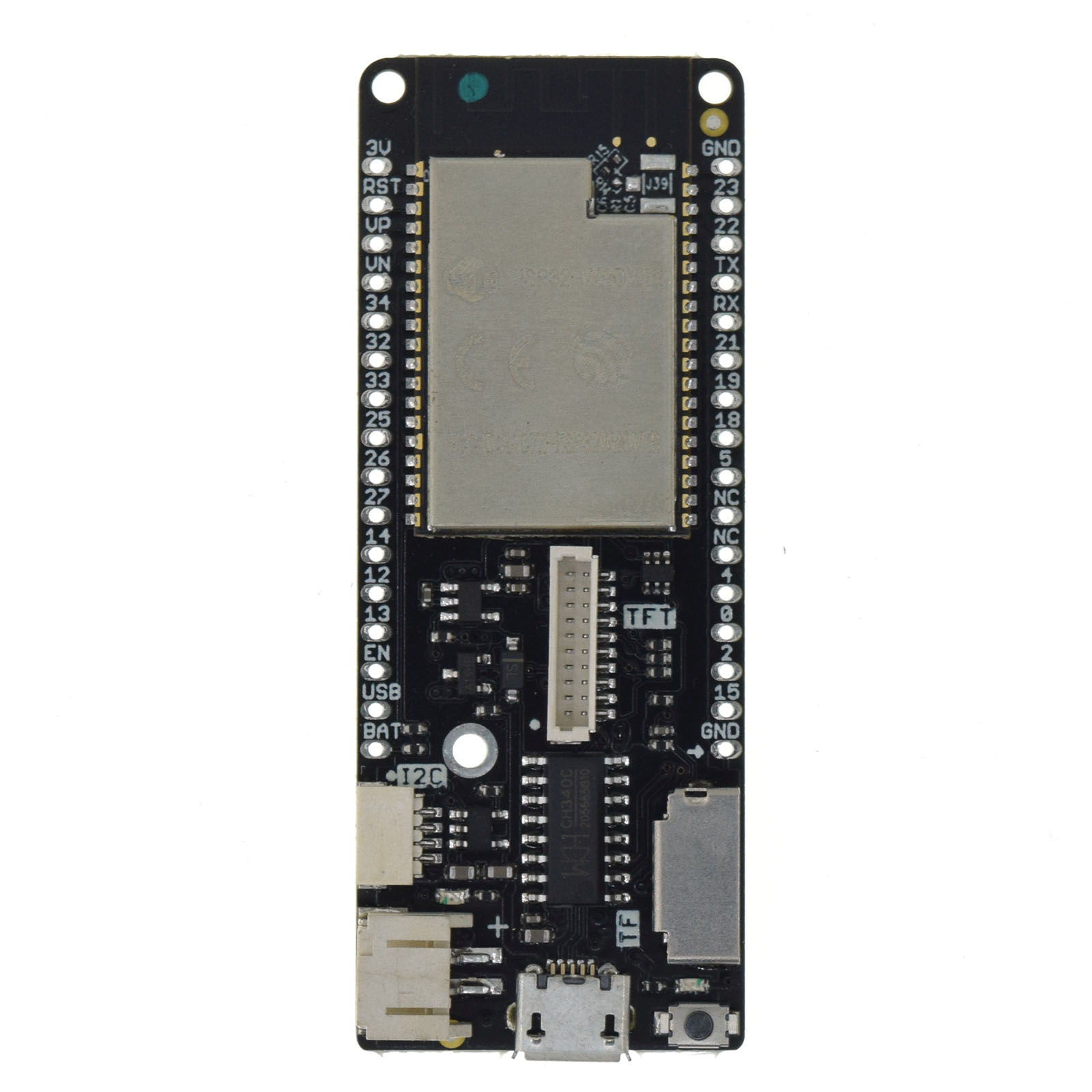
Board Pinout
The following picture shows the pinout of WEMOS LOLIN D32 PRO board as defined by the default board configuration. The light green GPIOs are not used by configured on-board hardware components and can be used for any purpose. However, if optional off-board hardware modules are used, these GPIOs may also be occupied, see section Board Configuration for more information.
The corresponding board schematic can be found here.

Flashing the Device
Flashing RIOT is quite easy. The board has a Micro-USB connector with reset/boot/flash logic. Just connect the board to your host computer using the programming port and type:
For detailed information about ESP32 as well as configuring and compiling RIOT for ESP32 boards, see RIOT-OS on ESP32 SoC Series Boards.
Files | |
| file | arduino_iomap.h |
| Mapping from MCU pins to Arduino pins. | |
| file | board.h |
| Board specific definitions for Wemos LOLIN D32 Pro. | |
| file | gpio_params.h |
| Board specific configuration of direct mapped GPIOs. | |
| file | periph_conf.h |
| Peripheral MCU configuration for Wemos LOLIN D32 Pro. | |
