Support for the Olimex MOD-WIFI-ESP8266-DEV board. More...
Detailed Description
Support for the Olimex MOD-WIFI-ESP8266-DEV board.
Overview
Olimex MOD-WIFI-ESP8266-DEV is a tiny development board that is available as open-source hardware at GitHub. It uses Espressif's ESP8266EX SoC and was originally designed to add WiFi capabilities to existing boards.
Olimex MOD-WIFI-ESP8266-DEV belongs to the class of general purpose boards where all ESP8266EX pins are broken out for easier access. The board can either be soldered directly to a PCB or it can be used with a breadboard.

The board provides some pads for an UEXT interface. UEXT interface (introduced by Olimex) can be used to connect different peripherals to the board. This UEXT interface comprises the 3 serial interfaces UART, SPI and I2C. For more information about UEXT, see UEXT.
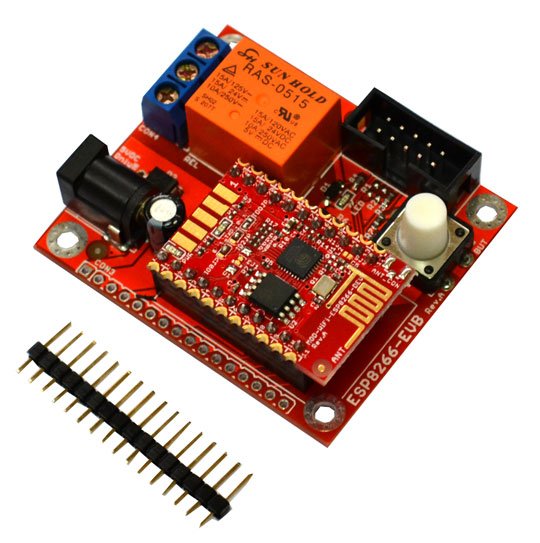
Together with the Olimex ESP8266-EVB evaluation board, a development platform for IoT devices is available.
Hardware
MCU
Most features of the board are provided by the ESP8266EX SoC.
| MCU | ESP8266EX |
|---|---|
| Family | Tensilica Xtensa LX106 |
| Vendor | Espressif |
| RAM | 80 kByte |
| Flash | 2 MByte |
| Frequency | 80 / 160 MHz |
| FPU | no |
| Timers | 1 x 32 bit |
| ADCs | 1 x 10 bit (1 channel) |
| LEDs | 1 x GPIO1 |
| I2Cs | 2 (software implementation) |
| SPIs | 1 |
| UARTs | 1 (console) |
| WiFi | built in |
| Vcc | 2.5 - 3.6 V |
| Datasheet | Datasheet |
| Technical Reference | Technical Reference |
| Board Schematic | Board Schematic |
- Note
- For detailed information about ESP8266, see RIOT-OS on ESP8266 and ESP8285 boards.
RIOT Pin Mapping
Olimex MOD-WIFI-ESP8266-DEV has 22 pin holes that can be soldered to PCB or used with a breadboard. The following figure shows the mapping of these pin holes to RIOT pins.

Since GPIOs 6, 7, 8, and 11 are used for flash memory, they cannot be used for other purposes. Furthermore, when flash mode qout or qio is used for flash memory, GPIOs 9 and 10 are used for flash memory additionally and cannot be used for other purposes, see section Flash Modes in RIOT-OS on ESP8266 and ESP8285 boards.
Flashing the Device
To flash the RIOT image, the device must be connected to the host computer through an FTDI USB to Serial adapter/cable connected to the device's UART interface, GPIO1 (TxD) and GPIO3 (RxD) ,
- Note
- Please make sure the FTDI USB to Serial adapter/cable uses 3.3 V.
Once the device is connected to the host computer, it must be booted into UART mode where the firmware can be downloaded via the UART interface. For this purpose, GPIO15 (MTD0) and GPIO0 must be pulled down and GPIO2 must be pulled up while the device is restarted using the RSTB pin. Since GPIO15 (MTDO) is pulled down and GPIO0 as well as GPIO2 are pulled up by solder bridges, only GPIO0 needs to be pulled down while the device is being reset with the RSTB pin.
To flash the RIOT image just type:
For detailed information about ESP8266 as well as configuring and compiling RIOT for ESP8266 boards, see RIOT-OS on ESP8266 and ESP8285 boards.
Files | |
| file | arduino_iomap.h |
| Board specific configuration for the Arduino API. | |
| file | board.h |
| Board specific definitions for Olimex MOD-WIFI-ESP8266-DEV boards. | |
| file | gpio_params.h |
| Board specific configuration of direct mapped GPIOs. | |
| file | periph_conf.h |
| Board specific configuration of MCU periphery for Olimex MOD-WIFI-ESP8266-DEV boards. | |
