
SeeedStudio SenseCAP T1000-E
Support for the SeeedStudio SenseCAP T1000-E
Support for the SeeedStudio SenseCAP T1000-E @author Baptiste Le Duc baptiste.leduc@etik.com
Pin configuration is based on the Meshtastic firmware variant for this board.
Overview
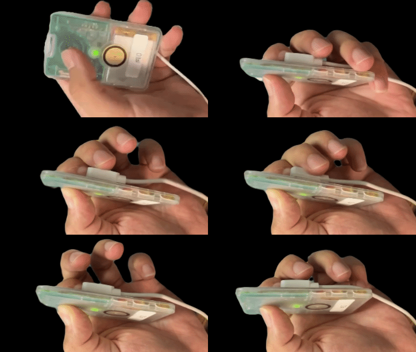
The SenseCAP T1000-E is a compact LoRaWAN tracker based on the nRF52840 MCU with the following on-board components:
- Nordic nRF52840 SoC @64MHz, 1MB Flash, 256KB RAM
- Semtech LR1110 LoRa transceiver
- Mediatek AG3335 GNSS module
- QMA6100P 3-axis accelerometer
- NTC temperature sensor
- Light sensor
- Buzzer
- 1 user button
- 1 LED
- LiPo battery support with charging detection
Hardware
| MCU | nRF52840 | Supported |
|---|---|---|
| Family | ARM Cortex-M4 with FPU | |
| Vendor | Nordic Semiconductor | |
| RAM | 256 KByte | |
| Flash | 1 MByte | |
| Frequency | 64 MHz | |
| FPU | yes | yes |
| Timers | 5 (32-bit) | yes |
| RTC | 3 | yes |
| ADC | 12-bit SAADC, 8 channels | yes |
| UART | 2 x UARTE | yes |
| SPI | 3 x SPIM | yes |
| I2C | 2 x TWIM | yes |
| PWM | 4 x PWM (4 ch each) | yes |
| USB | 1 x Full Speed | yes |
| BLE | Bluetooth 5.0 | yes |
| IEEE 802.15.4 | yes | yes |
| Vcc | 1.7V - 3.6V | |
| Datasheet | nRF52840 Product Specification | |
| Board Manual | SenseCAP T1000-E Wiki |
Pin Layout / Configuration
| RIOT Peripheral | MCU Pin | Board Function | Remark |
|---|---|---|---|
| BTN0 | P0.06 | User button | pull-down, active high |
| LED0 | P0.24 | LED | |
| UART_DEV(0) RX | P0.14 | GNSS (AG3335) RX | |
| UART_DEV(0) TX | P0.13 | GNSS (AG3335) TX | |
| UART_DEV(1) RX | P0.17 | spare / debug RX | |
| UART_DEV(1) TX | P0.16 | spare / debug TX | |
| SPI_DEV(0) SCLK | P0.11 | LR1110 SCLK | |
| SPI_DEV(0) MOSI | P1.09 | LR1110 MOSI | |
| SPI_DEV(0) MISO | P1.08 | LR1110 MISO | |
| I2C_DEV(0) SCL | P0.27 | QMA6100P SCL | |
| I2C_DEV(0) SDA | P0.26 | QMA6100P SDA | |
| PWM_DEV(0) CH0 | P0.25 | Buzzer | |
| NRF52_AIN0 | P0.02 | Battery voltage ADC | |
| NRF52_AIN5 | P0.29 | Light sensor ADC | |
| NRF52_AIN7 | P0.31 | NTC temperature ADC | |
| T1000E_LORA_NSS_PIN | P0.12 | LR1110 chip select | |
| T1000E_LORA_RESET_PIN | P1.10 | LR1110 reset | |
| T1000E_LORA_IRQ_PIN | P1.01 | LR1110 IRQ (DIO1) | |
| T1000E_LORA_BUSY_PIN | P0.07 | LR1110 busy (DIO2) | |
| T1000E_GPS_EN_PIN | P1.11 | GNSS power enable | |
| T1000E_GPS_RESET_PIN | P1.15 | GNSS reset | |
| T1000E_3V3_EN_PIN | P1.06 | Sensor 3V3 power enable | |
| T1000E_3V3_ACC_EN_PIN | P1.07 | Accelerometer power enable | |
| T1000E_ACC_INT_PIN | P1.02 | QMA6100P interrupt | |
| T1000E_CHRG_DETECT_PIN | P1.03 | Charging status | |
| T1000E_EXT_PWR_DETECT_PIN | P0.05 | External power detect |
Flashing the Device
The T1000-E ships with the Adafruit nRF52 Bootloader, you can find flashing instructions Adafruit nRF52 Bootloader section.
DFU mode must be entered manually before flashing. Follow the SeeedStudio instructions to put the device in DFU mode, then run:
BOARD=seeedstudio-sensecap-t1000e make -C examples/basic/hello-world flashNote: Accessing the SWD pads requires opening the device enclosure. Overwriting the bootloader via SWD would make UF2 flashing unavailable and is not recommended for normal use.
Accessing STDIO
By default, stdio uses UART_DEV(1) (P0.16/P0.17).
UART_DEV(0) is reserved for the GNSS module. Connect a USB-to-UART adapter
to P0.16 (TX) and P0.17 (RX) to access the terminal.
To use USB CDC ACM (virtual serial port over the existing USB cable) instead,
you can add USEMODULE+=stdio_cdc_acm to your application’s Makefile or to
the compiler call:
USEMODULE=stdio_cdc_acm BOARD=seeedstudio-sensecap-t1000e make -C examples/basic/hello-world flash term