phyWAVE-KW22 Board
Support for the phyWAVE evaluation board
Support for the phyWAVE evaluation board
Manufacturer
Designed and produced by PHYTEC Messtechnik GmbH, D-55129 Mainz. Homepage | Ordering information via mail at contact@phytec.de
Overview
The phyNODE evaluation board consists of a phyWAVE module mounted on a common PCB with several sensor and actuator modules. The board provides 2 USB ports. The one next to the white imprint cmsis-dap is meant for development (debug and flash). The second one, next to the golden PHYTEC imprint, is connected to the USB peripheral of the MCU and may be used by a firmware (currently not supported).
The implementation status of the phyWAVE and phyNODE peripherals are listed below. You can find links to the corresponding Pull Requests which may give you a code reference.
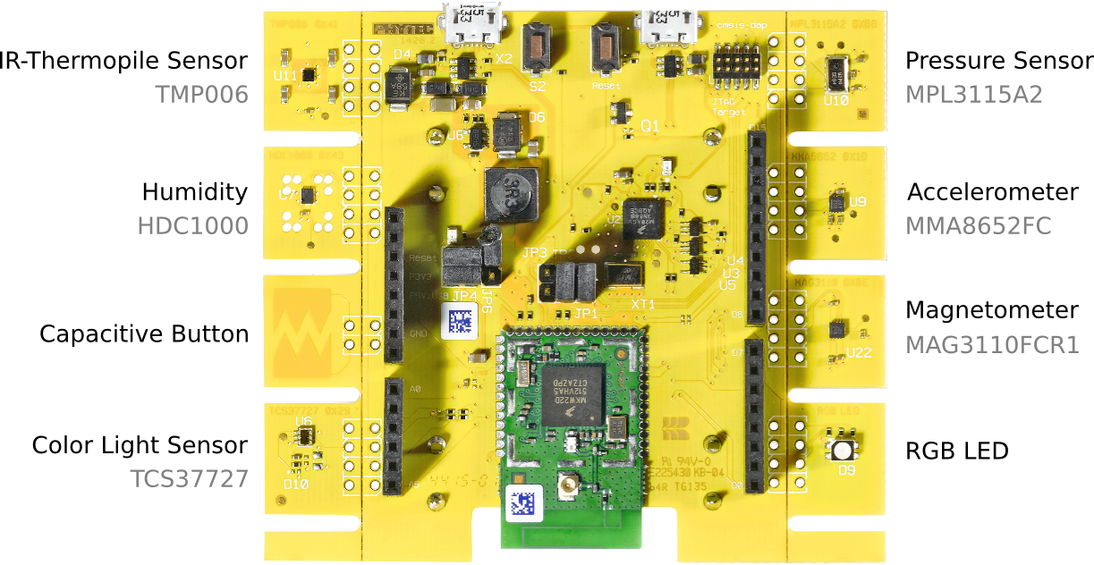
Note: The PCB-pieces with the mounted sensors can be separated from the evaluation board to capture sensor values from specific spatial points.
Pinout Reference
The board features an Arduino like header connector to mount shields. The spacing of the 4 pin rows is a bit offset, thus shields might not fit perfectly.
The pinout below shows the vendor specific naming and functionality. The actual pin configuration of the board for RIOT can be found in periph_conf.h.
Note: Not all signals and pins are compatible with Arduino Uno R3.
_X1____________________ | D15 |___DIO21, PE19, I2C0 SCL | D14 |___DIO20, PE18, I2C0 SDA | AREF |___AREF, VCC3V3 | GND3 |___GND X___| RESERVED D13 |___DIO3, PC5, SPI0 SCK VCC3V3___| IOREF D12 |___DIO5, PC7, SPI0 MISO nRESET___| RST TGTMCU D11 |___DIO4, PC6, SPI0 MOSI VCC3V3___| P3V3 D10 |___DIO2, PC4, SPI0 CS0 P5V USB OUT___| P5V USB D9 |___DIO9, PD4, PWM GND_________| GND2 D8 |___DIO6, PD1 \___| GND1 | X___| P5_9V VIN D7 |___DIO24, PA1, PWM, TDI2 | D6 |___DIO25, PA2, PWM, TDO2 DIO15, PE2, ADC ___| A0 D5 |___DIO11, PD6, PWM DIO16, PE3, ADC, TDO1 ___| A1 D4 |___DIO29, PA19, TCLKIN DIO12, PD7, ADC ___| A2 D3 |___DIO27, PA4, PWM DIO10, PD5, ADC ___| A3 D2 |___DIO17, PE4, LLWU, TDI1 DIO13, PE0, ADC, I2CSDA ___| A4 D1 |___DIO8, PD3, UART2 TX DIO14, PE1, ADC, I2CSCL ___| A5 D0 |___DIO7, PD2, UART2 RX ----------------------- Arduino Uno R3 ConnectorImplementation Status
| Device | ID | Supported | Comments |
|---|---|---|---|
| MCU | MKW22D512 | yes | mainline |
| phyWAVE board support | phyWAVE | yes | mainline |
| Low-level driver | GPIO | yes | mainline |
| PWM | yes | mainline | |
| UART | yes | mainline | |
| I2C | yes | mainline | |
| SPI | yes | mainline | |
| USB-Device | yes | WIP | |
| RTT | yes | mainline | |
| RNG | yes | mainline | |
| Timer | yes | mainline | |
| Radio Chip | integrated | yes | mainline |
| Humidity Sensor | HDC1000 | yes | mainline |
| Pressure Sensor | MPL3115A2 | yes | mainline |
| Tri-axis Accelerometer | MMA8652FC | yes | mainline |
| Magnetometer | MAG3110FCR1 | yes | mainline |
| Light Sensor | TCS3772 | yes | mainline |
| IR-Termopile Sensor | TMP006 | yes | mainline |
| Capacitive Button | PCB | yes | mainline |