Microduino CoreRF
Support for the Microduino CoreRF board
Support for the Microduino CoreRF board
Hardware
Pinout
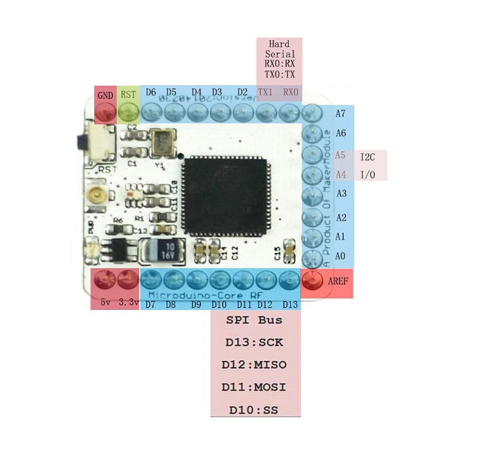
Warning: Unlike on other ATmega MCUs, the GPIOs are not 5V tolerant.
Note: The 5V pin cannot be used to power the board, as the board is not equipped with an voltage regulator. The pin is therefore not connected. But it can be used to pass 5V to shields, if connected to a 5V supply voltage.
Board
The board is just a breakout for the ATmega128RFA1 MCU.
MCU Details
| MCU | ATmega128RFA1 |
|---|---|
| Family | ATmega |
| Vendor | Atmel |
| Package | QFN/MLF |
| SRAM | 16KiB |
| Flash | 128KiB |
| EEPROM | 4KiB |
| Core Frequency | 8MHz (16MHz no power save mode) |
| Oscillators | 32.768 kHz & 16 MHz |
| Timer | 6 ( 2x8bit & 4x16bit ) |
| Analog Comparator | 1 |
| ADCs | 1x 15 channel 6 to 12-bit |
| USARTs | 2 |
| SPIs | 3 (1 SPI & 2 USART SPI) |
| I2Cs | 1 (called TWI) |
| Vcc | 1.8V - 3.6V |
| Datasheet / Reference Manual | Datasheet and Reference Manual |
| Board Manual | Wiki Page |
The MCU comes with a 2.4 GHz IEEE 802.15.4 radio that is compatible with the Atmel AT86RF23x line of transceivers with the only difference being that it is not being accessed over an SPI bus, but instead the radio registers are directly mapped into memory.
Peripheral interfaces SPI and I2C
According to the wiki, SPI and I2C pins are the following:
| SPI | Original Pin Name | Map Pin Name |
|---|---|---|
| SS | PB4 | D10 |
| MOSI | PB2 | D11 |
| MISO | PB3 | D12 |
| SCK | PB1 | D13 |
| I2C | Original Pin Name | Map Pin Name |
|---|---|---|
| SDA | PD1 | D18 |
| SCL | PD0 | D19 |
Flashing RIOT
Flashing RIOT on the CoreRF is done using the SPI method. Using a cheap FT232H breakout board, connect the board as follows:
| FT232H | Microduino CoreRF |
|---|---|
| D0 | D13 (SCK) |
| D1 | D11 (MOSI) |
| D2 | D12 (MISO) |
| D3 | RST (Reset) |
| 3.3V | 3.3V |
| GND | GND |
Now you can simply type
make flash BOARD=microduino-corerf
This should take care of everything!
You will need a separate adapter for UART:
| FT232R | Microduino CoreRF |
|---|---|
| TX | D0 |
| RX | D1 |
Troubleshooting
Using the external crystal oscillator (Transceiver Crystal Oscillator) and deep sleep
When the external crystal oscillator is used as system clock and the device is put into deep sleep mode it seems that the clocks for all peripherals are enabled and set to the smallest divider (highest frequency). This leads to a higher power consumption. When the device should be put into deep sleep it is recommended to use the internal RC oscillator as system clock source.
Pin Change Interrupts
More pins can be used for hardware interrupts using the Pin Change Interrupt feature. See boards_common_atmega for details.
Debugging
The ATmega128RFR1 supports JTAG debugging. To use the JTAG debugging an external JTAG debugger is required. There are several options for this MCU/board:
Hint: The AVR Dragon is the cheapest least expensive debugger and also is
compatible with almost every AVR MCU.
Warning: With the default fuse settings, on chip debugging is disabled.
Note: If you are using a different debugger than the AVR Dragon, you have
to export the AVR_DEBUGDEVICE environment variable to the required
flag to pass to AVaRICE, e.g. when using the Atmel-ICE you have to
export AVR_DEBUGDEVICE=--edbg. If the debug device is not
connected via USB, you also need to export AVR_DEBUGINTERFACE to
the correct value.
JTAG Pin Mapping
| Pin | Pin Label | Signal | AVR Dragon Pin |
|---|---|---|---|
| PF7 | A0 | TDI | JTAG-9 |
| PF6 | A1 | TDO | JTAG-3 |
| PF5 | A2 | TMS | JTAG-5 |
| PF4 | A3 | TCK | JTAG-1 |
| VDD | 3V3 | VTG | JTAG-4 |
| GND | GND | GND | JTAG-2 |
Fuse Settings
Be aware that changing the fuse settings can “brick” your MCU, e.g. if you select a different clock setting that is not available on your board. Or if you disable all options for programming the MCU.
You can always de-brick your MCU using high voltage programming mode, which can also be done using the AVR Dragon. But being careful to not brick your MCU in the first place is clearly the better option ;-)
In the following it is assumed that you connect the Dragon ISP header to the Microduino CoreRF for ISP programming.
Default Fuse Settings
The default fuse settings of the Microduino CoreRF are: E:F5, H:DA, L:FF.
These settings can be restored via from the OCD settings via:
avrdude -c dragon_isp -p m128rfa1 -U hfuse:w:0xda:mIf you touched other fuse settings, you can restore the fuse settings using:
avrdude -c dragon_isp -p m128rfa1 -U efuse:w:0xf5:m -U hfuse:w:0xda:m -U lfuse:w:0xff:mOn-Chip Debugging Fuse Settings
To enable on-chip debugging, the JTAGEN (enable JTAG) and the OCDEN (enable
on-chip debugging) bits should be set: E:F5, H:1A, L:FF. This can be done
(when starting with the default settings) via:
avrdude -c dragon_isp -p m128rfa1 -U hfuse:w:0x1a:m