ESP32-S2-DevKit Board
Support for generic ESP32S2 boards
Support for generic ESP32S2 boards @author Gunar Schorcht gunar@schorcht.net
\section esp32s2_devkit ESP32-S2-DevKit
Overview
The Espressif ESP32-S2-DevKit boards are a couple of boards that use one of the following modules:
- ESP32-S2-MINI-1x-N4 module (ESP32-S2-DevKitM-1 board)
- ESP32-S2-MINI-1x-N4R2 module (ESP32-S2-DevKitM-1R board)
- ESP32-S2-SOLO-N4 module (ESP32-S2-DevKitC-1 board)
- ESP32-S2-SOLO-N4R2 module (ESP32-S2-DevKitC-1R board)
- ESP32-S2-WROOM module (ESP32-S2-Saola-1 board)
- ESP32-S2-WROVER-N4R2 module (ESP32-S2-Saola-1R board)
Due to the different modules used, the available versions of the ESP32-S2-DevKit board differ regarding the Flash size, the integrated SPI RAM and the SPI voltage. To be able to use all these different versions of the board with a single board definition, used board version can be specified by the variable `BOARD_VERSION` during compilation, for example:
BOARD=esp32s2-devkit BOARD_VERSION=esp32s2-devkitc-1r make ...The following table shows the available board versions, the size of the
Flash and the SPI RAM as well as the value of the variable BOARD_VERSION
that is used to specify the board version.
@note
- If the board version is not specified, ESP32-S2-DevKitM-1 with 4 MByte
Flash is assumed and
BOARD_VERSIONis set toesp32s2-devkitm-1by default. - Using a board version with embedded SPI RAM (
BOARD_VERSIONis any ofesp32s2-*-1r*values) enables the esp32_spi_ram “esp_spi_ram” feature. The SPI RAM can then be used as heap by enabling the esp32_spi_ram “esp_spi_ram” pseudomodule.
Hardware
MCU
Most features of the board are provided by the ESP32-S2 SoC. For detailed information about the ESP32-S2 SoC variant (family) and ESP32x SoCs, see section esp32_mcu_esp32 “ESP32 SoC Series”.
Board Configuration
ESP32-S2-DevKit boards have no special hardware on board with the exception of a single pin RGB-LED.
All GPIOs are simply broken out for flexibility. Therefore, the board configuration is the most flexible one which provides:
- 20 x ADC channels at maximum
- 2 x SPI
- 1 x I2C
- 2 x UART
- 1 RGB-LED
Since almost GPIOs have broken out, GPIOs can be used for different purposes in different applications. Following GPIOs are used for Flash and SPI RAM and are not broken out:
- ESP32-S2-DevKitC-1x: GPIO27..GPIO32
- ESP32-S2-DevKitM-1x: GPIO26..GPIO32
- ESP32-S2-Saola-1x: GPIO26..GPIO32
For flexibility, GPIOs can be used in multiple peripheral configurations, but they can only be used for one peripheral at a time. For example, GPIO9 is used in the ADC channel definition and the definition of the SCL signal for I2C_DEV(0).
This is possible because GPIOs are only used for a specific peripheral interface when either
- the corresponding peripheral module is used, e.g.
periph_i2c, or - the corresponding init function is called, e.g.
adc_init.
That is, the purpose for which a GPIO is used depends on which module or function is used first.
For example, if module periph_i2c is not used, the GPIOs listed in I2C
configuration can be used for the other purposes, that is, GPIO9 can be
used as ADC channel.
The following table shows the default board configuration, which is sorted according to the defined functionality of GPIOs. This configuration can be overridden by esp32_application_specific_configurations “application-specific configurations”.
For detailed information about the peripheral configurations of ESP32-S2 boards, see section esp32_peripherals “Common Peripherals”.
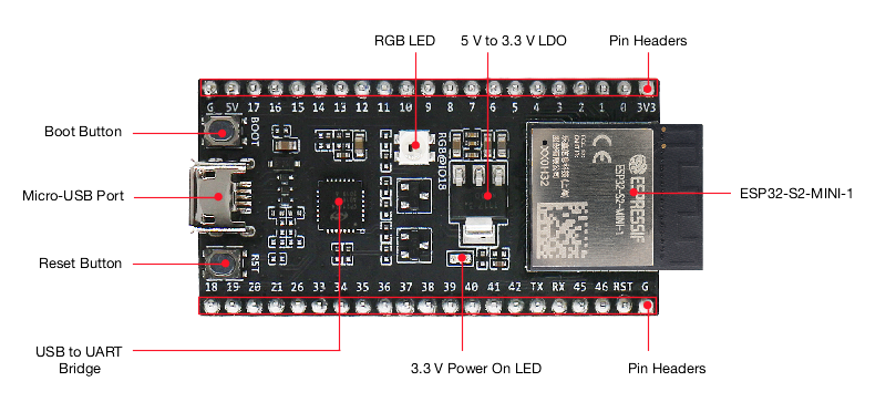
Board Pinout
The following figures show the pinouts as configured by default board definition.
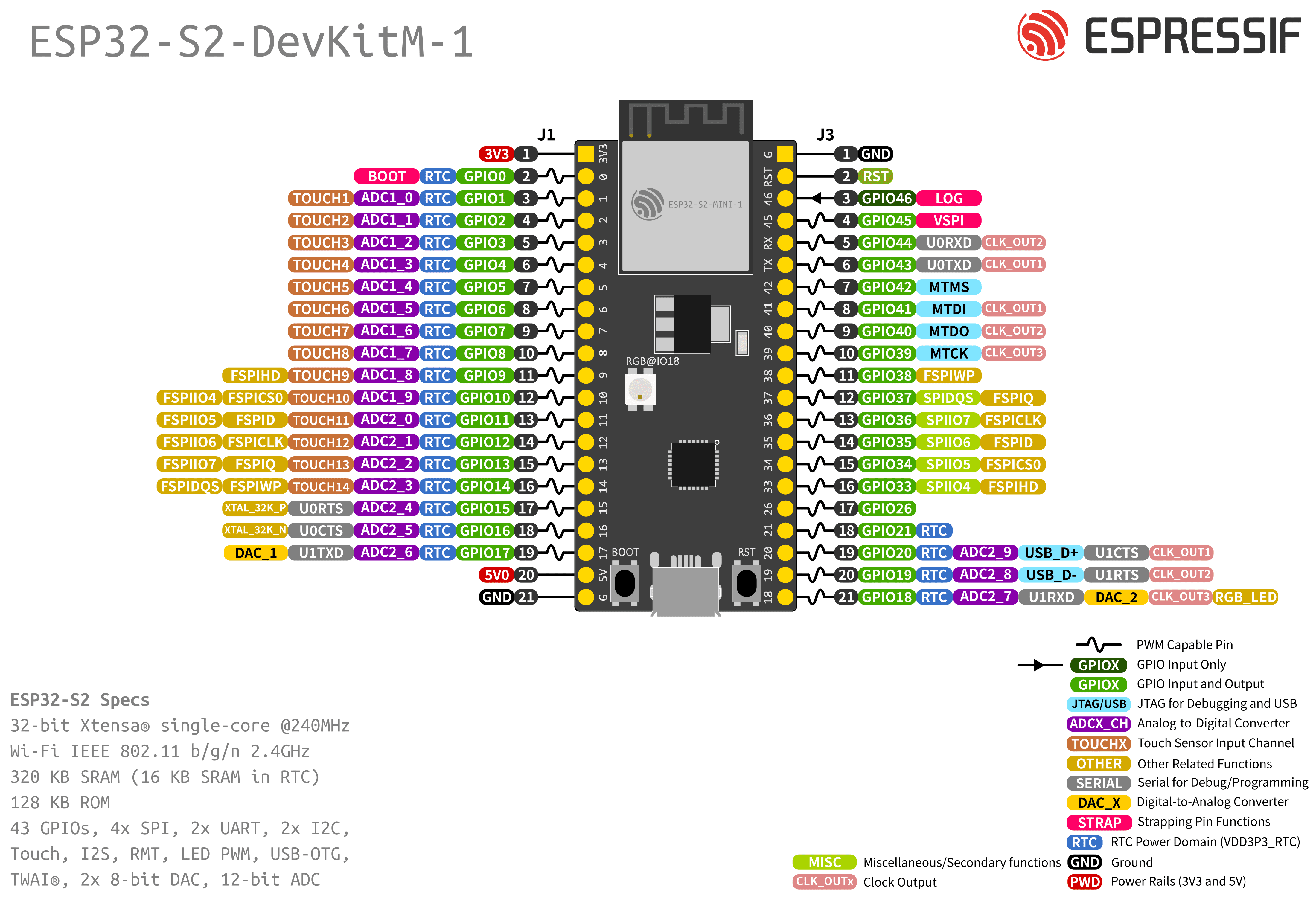
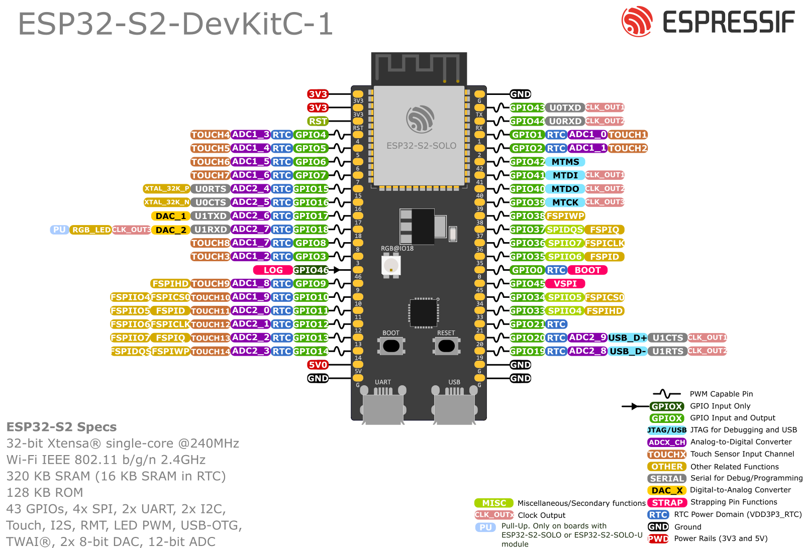
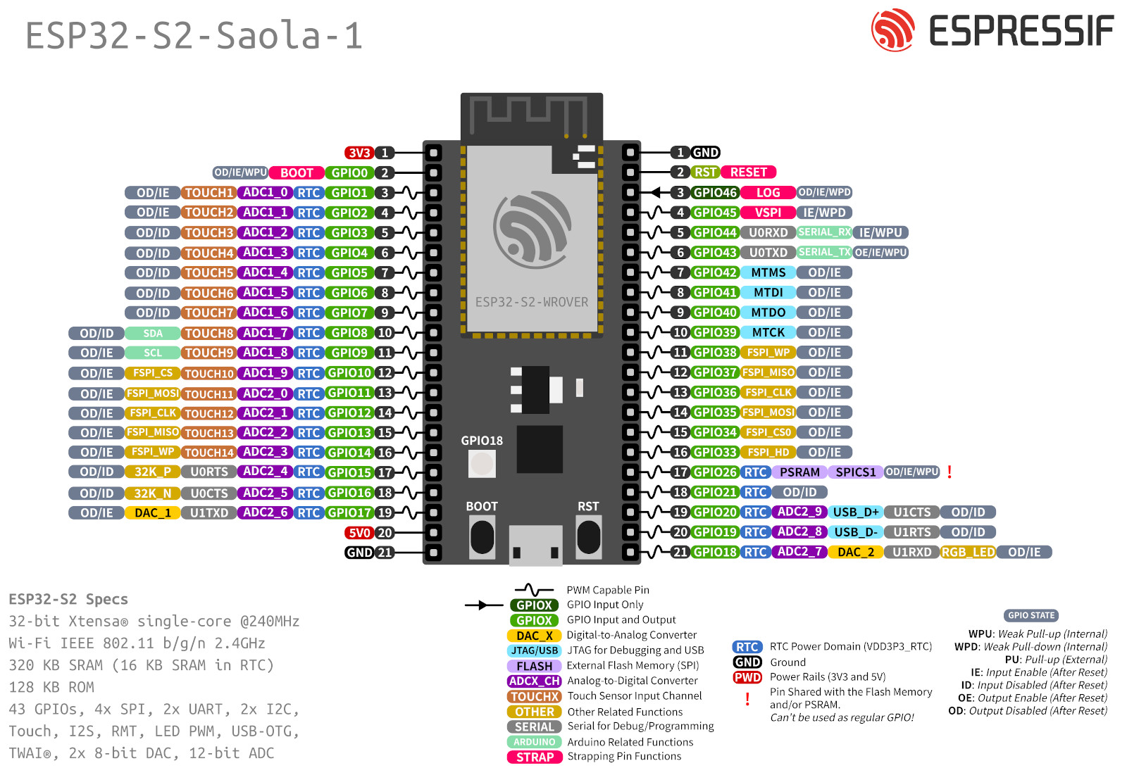
The corresponding board schematics can be found:
Flashing the Device
Flashing RIOT is quite easy. The board has a Micro-USB connector with reset/boot/flash logic. Just connect the board to your host computer and type using the programming port:
BOARD=esp32s2-devkit make flash ...For detailed information about ESP32-S2 as well as configuring and compiling RIOT for ESP32-S2 boards, see esp32_riot.