ESP32-C6-DevKit Board
Support for generic ESP32-C6 boards
Support for generic ESP32-C6 boards @author Gunar Schorcht gunar@schorcht.net
\section esp32c6_devkit ESP32-C6-DevKit
Overview
The Espressif ESP32-C6-DevKit boards are a couple of boards that use one of the following modules:
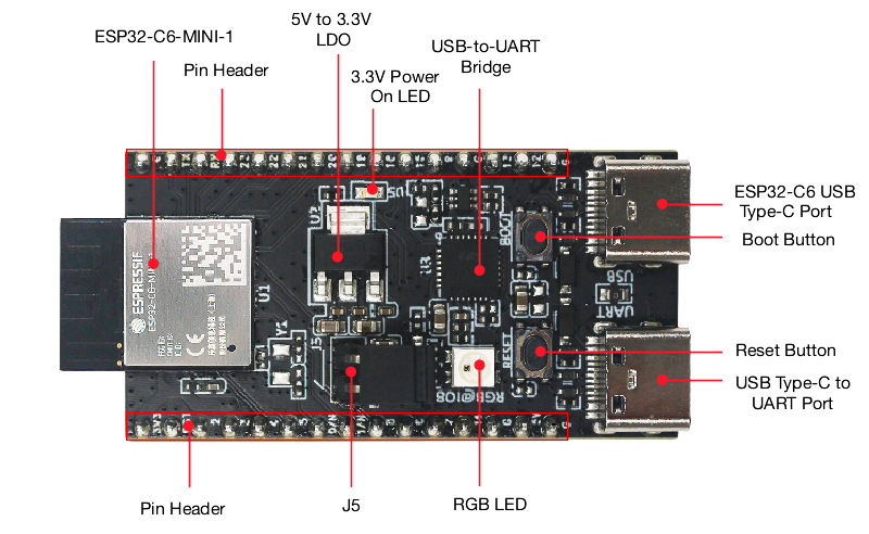
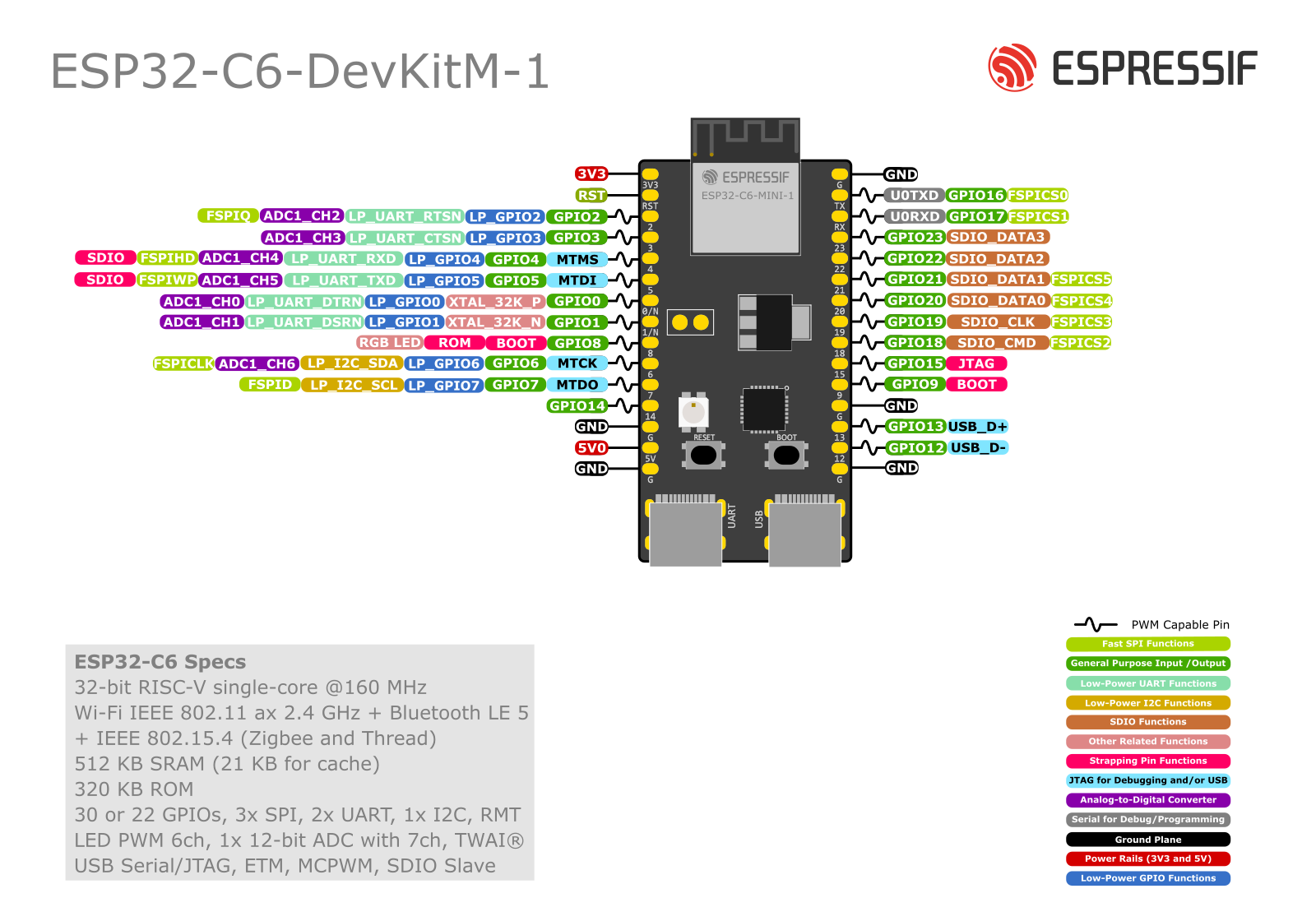
- ESP32-C6-MINI-1x module (ESP32-C6-DevKitM-1 board)
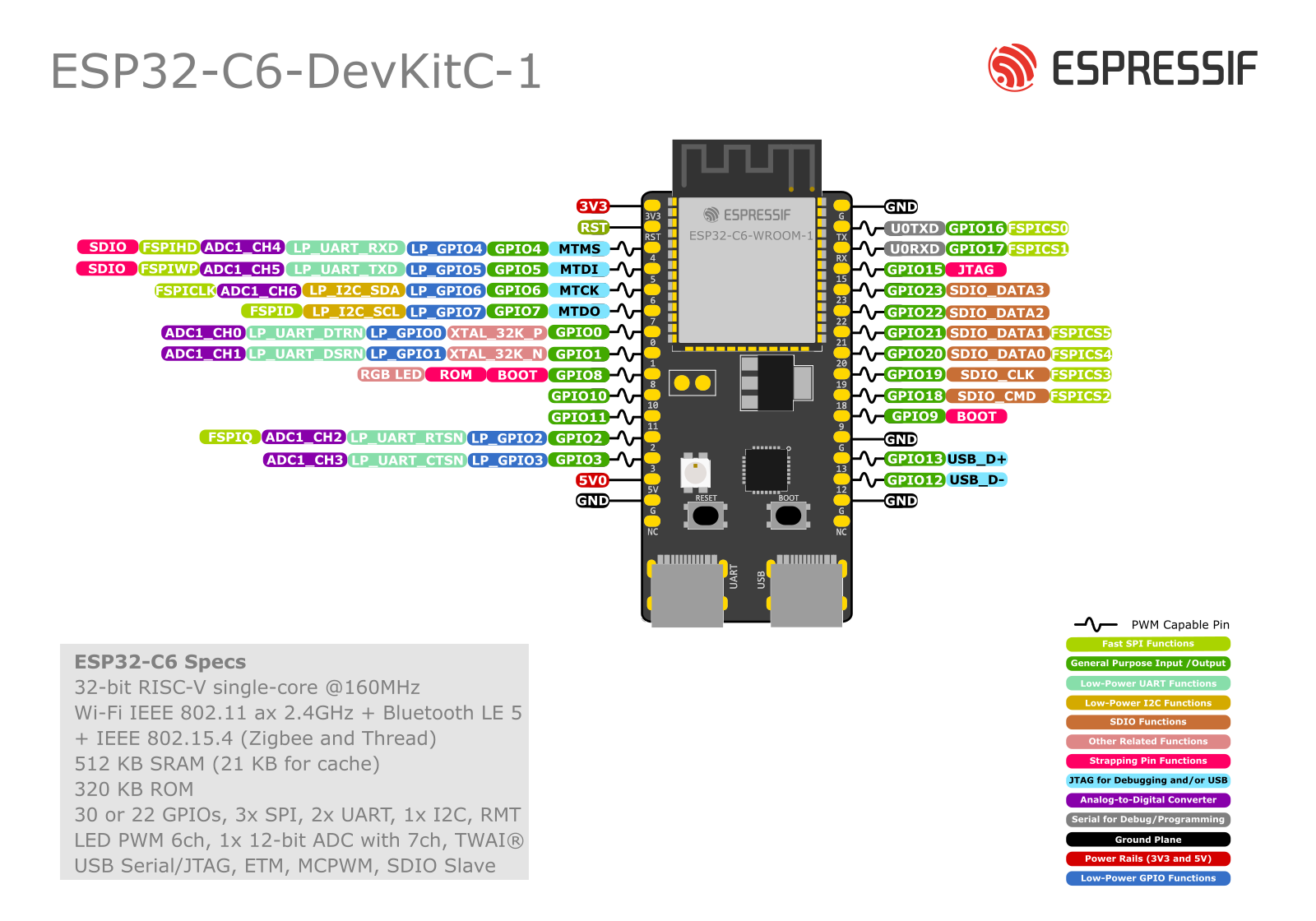
- ESP32-C6-WROOM-1x module (ESP32-C6-DevKitC-1 board)
Since the number of GPIOs and their possible uses on the ESP32-C6 are quite limited, the ESP32-C6-DevKit should also work for most other ESP32-C6 boards. Any modifications required for specific applications could be overridden by esp32_application_specific_configurations “application-specific board configuration”.
Hardware
MCU
Most features of the board are provided by the ESP32-C6 SoC. For detailed information about the ESP32-C6 variant (family) and ESP32x SoCs, see section esp32_mcu_esp32 “ESP32 SoC Series”.
Board Configuration
ESP32-C6-DevKit boards have no special hardware on board with the exception of a WS2812-compatible RGB-LED.
All GPIOs are simply broken out for flexibility. Therefore, the board configuration is the most flexible one which provides:
- 7 x ADC channels at maximum
- 1 x SPI
- 1 x I2C
- 1 x UART
- 2 x PWM with 3 channels each
- 1 x RGB-LED WS2812-compatible
Since all GPIOs are broken out, GPIOs can be used for different purposes in different applications. For flexibility, GPIOs can be used in multiple peripheral configurations, but they can only be used for one peripheral at a time. For example, GPIO4 and GPIO5 are defined as ADC channels and signals for I2C_DEV(0), GPIO7 and GPIO18 are defined as channels for PWM_DEV(1) and signals for SPI_DEV(0).
This is possible because GPIOs are only used for a specific peripheral interface when either
- the corresponding peripheral module is used, e.g.
periph_i2candperiph_spi, or - the corresponding init function is called, e.g.
adc_initandpwm_init.
That is, the purpose for which a GPIO is used depends on which module
or function is used first. For example, if module periph_i2c is not used,
the GPIOs listed in I2C configuration can be used for the other purposes,
that is, GPIO4 and GPIO5 can be used as ADC channels.
The following table shows the default board configuration, which is sorted according to the defined functionality of GPIOs. This configuration can be overridden by esp32_application_specific_configurations “application-specific configurations”.
@note - The configuration of ADC channels contains all ESP32-C6 GPIOs that could be used as ADC channels. - GPIO10, GPIO11 and GPIO24 to GPIO30 are used for internal flash and are not broken out. - GPIO0 and GPIO1 can be used to connect an external 32.678 kHz crystal. - GPIO15 is a strapping pin used to select the JTAG interface if `JTAG_SEL_ENABLE` is burned in the eFuses.
For detailed information about the peripheral configurations of ESP32-C6 boards, see section esp32_peripherals “Common Peripherals”.
Board Pinout
The following figures show the pinouts as configured by default board definition.
The corresponding board schematics can be found:
Flashing the Device
Flashing RIOT is quite easy. The board has a Micro-USB connector with reset/boot/flash logic. Just connect the board to your host computer using the programming port and execute command:
BOARD=esp32c6-devkit make flash ...For detailed information about ESP32-C6 as well as configuring and compiling RIOT for ESP32-C6 boards, see esp32_riot.