
ESP32-Ethernet-Kit V1.0 Board
Support for for Espressif ESP32-Ethernet-Kit v1.0
Related Boards
Support for for Espressif ESP32-Ethernet-Kit v1.0 @author Gunar Schorcht gunar@schorcht.net @author Erik Ekman eekman@google.com
\section esp32-ethernet-kit-v1_0 Espressif ESP32-Ethernet-Kit V1.0
Overview
The Espressif ESP32-Ethernet-Kit is a development board that uses the ESP32-WROVER-B module. Most important features of the board are
- 100 Mbps Ethernet via IP101G PHY
- USB bridge with JTAG interface
Furthermore, some GPIOs are broken out for extension. The USB bridge based on FDI FT2232HL provides a JTAG interface for OCD debugging through the USB interface. For flashing and debugging the board, see boards_esp32_esp-ethernet-kit common board documentation.
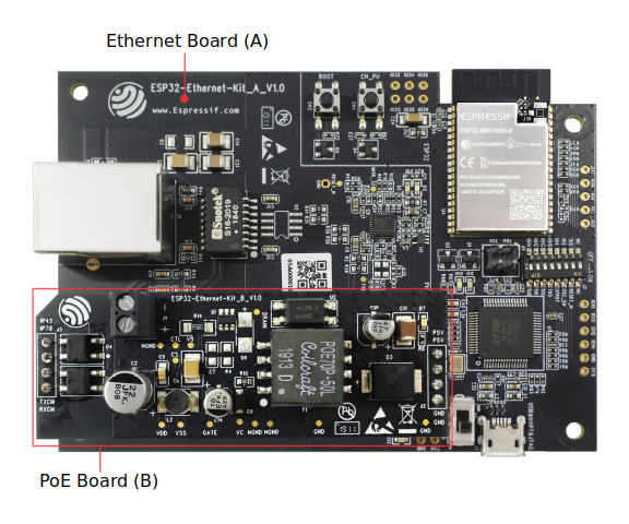
Hardware
Board Configuration
ESP32-Ethernet-Kit v1.0 has the following on-board components
- 100 Mbps Ethernet via IP101G PHY
- USB bridge with JTAG interface
For detailed information about the configuration of ESP32 boards, see section Peripherals in esp32_riot.
@note Only a few GPIOs are broken out and available for external hardware on ESP32-Ethernet-Kit boards. Which GPIOs are available as peripherals depends on used modules.
@note - GPIO4 only works properly on the board if the function switch for GPIO4 (DIP SW 5) is OFF. - SPI_DEV(0) is not available if module `esp_jtag` is used. For the SPI_DEV(0) pins to work properly, the function switches (DIP switches) for the JTAG signals must be set to OFF.
Board Pinout
The board schematic can be found here.
By default, only 3 bidirectional GPIO pins are unused: GPIO4, GPIO32, GPIO33. The suggested configuration is for PWM and I2C, but they can also be used for SPI or another serial port. By disabling the JTAG interface on the board, another 4 GPIOs can be made available (GPIO12, GPIO13, GPIO14, GPIO15).
Other Documentation Resources
There is a comprehensive Getting Started Guide for the ESP32-Ethernet-Kit with a lot information about hardware configuration.